
Electromagnetic Conductivity (EM) is a non-invasive method for mapping ground and subsurface conductivity and magnetic susceptibility. Identify aquifers, raised salinity, buried metallic objects, and shallow geological features.
Our conductivity meters operate on the basis of measuring changing impedance between a pair of electrical coils placed on, or carried above the earth’s surface. The equipment responds to variations in conductivity within the shallow ground subsurface caused by increased water content, presence of metallic and conductive materials.
Environmental applications for this type of survey include identifying specific conductive compounds or locating aquifers. Environmentally sensitive compounds that can be identified depend on concentrations of chloride, that can dramatically raise ground conductivity, either in the form of salt or PCE (tetrachloroethylene).
Locating aquifers and shallow water tables is a traditional use for conductivity surveys with wide applications in any form of land management, spanning agricultural, environmental, and engineering sectors.
Ground conductivity data forms an important component of building a comprehensive geophysical ground model. This data is typically used to develop plan view-heat maps showing areas of low to high conductivity. Collecting multiple data sets of the same survey area that specifically target different depths can provide an approximate 3D model of conductivity.
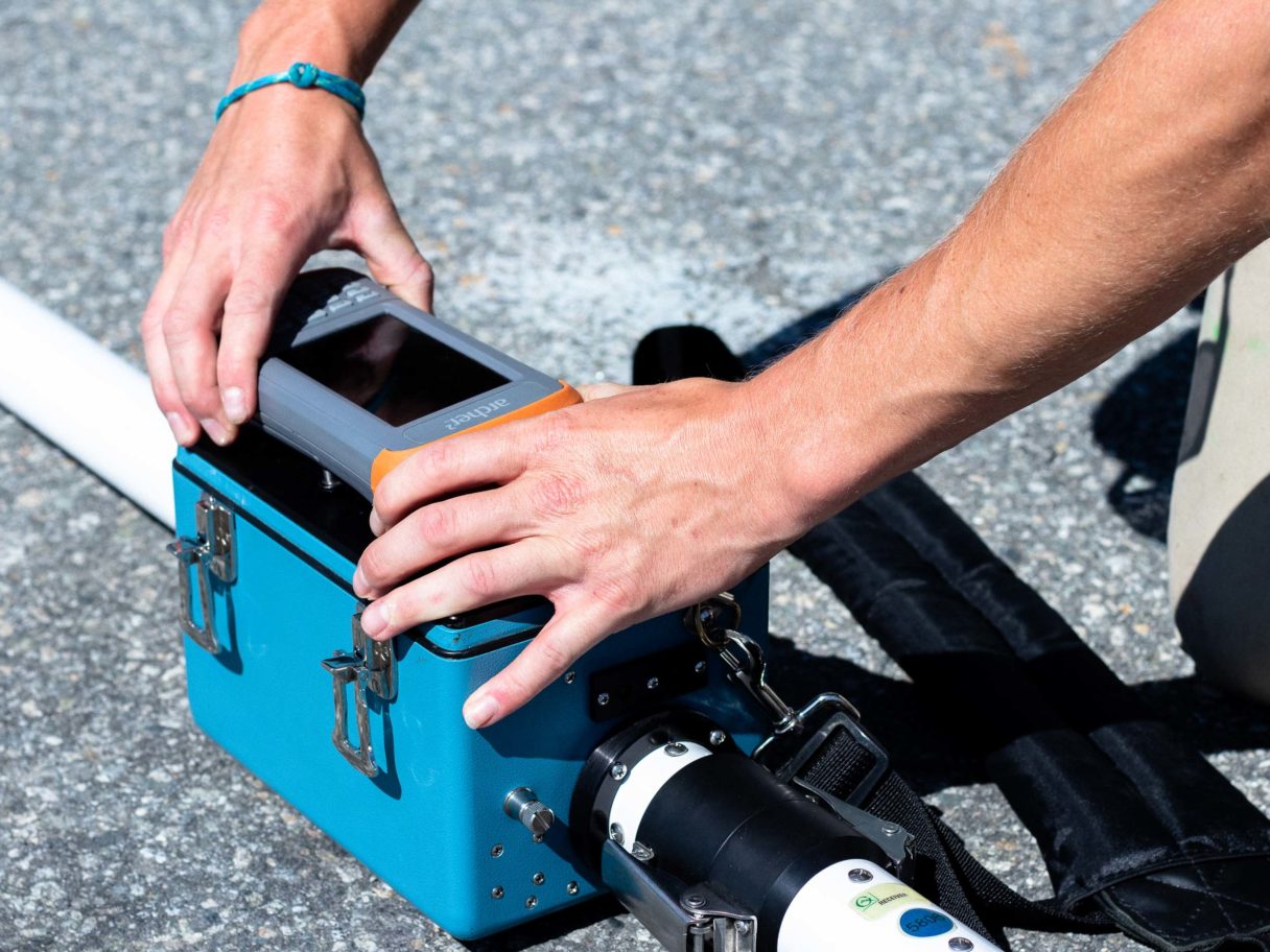
Lightweight handheld systems with GPS logging makes for speedy data collection even on rough terrain. Furthermore. this provides topographic data that can be utilized to project heat maps onto topo surfaces, ready to incorporate into 3D GIS, CAD or dedicated ground modelling software.
How it Works
Most Electromagnetic Conductivity (EM) instruments are comprised of two or more sets of coils; a transmitter and receiver. These two coils are electrically connected and are separated at a fixed distance. This distance determines the depth of investigation from shallow high resolution surveys at 0.4m down to 6m in depth.
The transmitter coil generates an electromagnetic field at a specific frequency, known as the primary field. The primary field causes electrical currents to flow in conductive materials in the subsurface. This flow of currents in the subsurface generates a secondary magnetic field, which is sensed by the receiver coil. The magnitude of the secondary field depends upon the type and distribution of conductive material in the subsurface.
The magnitude of the secondary field is broken into two orthogonal components: the in-phase and quadrature components. Under certain operating conditions, the magnitude of the quadrature component of the secondary field is linearly proportional to the apparent ground conductivity. In the absence of a highly conductive material, such as metallic targets in the subsurface, the magnitude of the in-phase component indicates the magnetic susceptibility of the materials within the subsurface.